
3.1.9 Axial and radial forces in pumps
Axial and radial forces in pumps
Axial and radial forces in pumps come mainly from forces developed from the impeller converting mechanical energy, torque from pump shaft, to hydraulic energy or in other words pressure and flow. The resulting axial force (thrust) on the pump shaft must be taken up by the bearing or balanced out with a special arrangement. A special balancing disc, however, always requires a certain amount of driving power and therefore reduces the overall efficiency of the pump. It is thus advantageous if the axial force can be limited directly by means of the pump impeller design. The application of the momentum equation (Equation 11.7) to a control volume, precisely that which encloses the impeller, gives us the following, using the terms as shown in figure 3.1.9a.


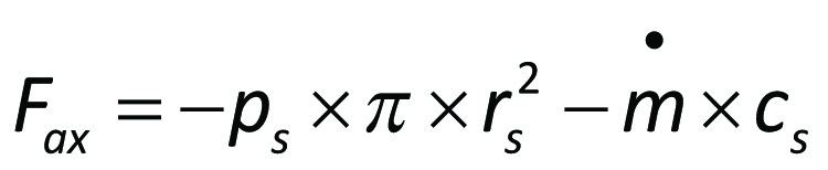
If the pressure on the front and back side of the impeller for r > rs is assumed to be equal (pb=pf) and if the angle β is small (sin β ~ 0) the above expression can be simplified to

A normal procedure in order to limit Fax is to provide the back side of the impeller with an extra sealing edge and at the same time to bore holes for pressure equalisation. Then
Besides the axial force from the impeller, the shaft is also subjected to forces from seals and bearings as well as the atmospheric pressure at the end of the shaft. The bearing
force is

Axial and radial forces in pumps can create substantial damages if not balanced. High pressures (ps) can result in large axial forces despite extra sealing edge and holes for pressure equalisation.

Another way of limiting the shaft forces is to provide the impeller with reverse side blades. This causes the co-rotation of the fluid on the reverse side to be greater than that achieved by friction on the front side. The increased co-rotation therefore causes lower pressure for r < r2 and also therefore a reduction in the actual force. In the case of multi-stage pumps or double suction pump impellers small axial forces are obtained by facing the impeller inlets in opposite directions.
Considerable radial forces occur during partial loading in all pumps equipped with volute casings. The design of such pumps seeks to achieve an even pressure distribution around the impeller. This condition determines the shape of the volute casing. During partial load, however, the pressure along the periphery of the impeller will vary. The radial forces on the impeller are taken up by the bearing via the shaft.

Figure 3.13 is an illustration of radial forces on the impeller in the case of reduced flow (Q<Qo). Qo is the volume flow at highest efficiency (BEP).
Since the pressure varies along the periphery of the impeller the flow in the different blade gaps will also vary as the impeller rotates. The size of the radial force can be estimated by means of the following formula:

where
Frad = radial force (N)
kF = dimensionless parameter
D₂ = outer diameter of impeller (m)
b₂ = outer width of impeller (m)
ρ = density of fluid (kg/m³)
g = acceleration due to gravity 9,806 (m/s²)
H = head (m)
The parameter kF assumes different values for different designs of pumps and also varies greatly with the volume flow through the pump.

Figure 3.15 exemplifies the effect of the position of the operating point and the shape of the volute casing on the parameter kF.
For a centrifugal pump with a single volute kF can assume a value up to 0.4 at shut of head, that is at zero discharge (Q=0).
An effective method of limiting the size of the radial force is to provide the volute casing with an extra intermediate wall (pump casing with a so-called double volute), figure 3.15.
The radial force is greatest at (shut-off head). The radial force causes a deflection of the pump shaft and subjects the shaft to rotary fatigue. The condition that the shaft deflection at the zero discharge should be less than 0.05 mm at the shaft seal is often used as guiding value in deciding the dimensions of the shaft.
The size of the axial and radial forces is a determining factor in the design construction of the pump (dimensions of clearances, bearings etc.). They are also often the primary cause of breakdowns. Note that both the axial and the radial forces increase with partial load and are greatest at zero discharge.