3.2 Centrifugal pump type
Classification of centrifugal pump type
Classification of centrifugal pump type can be done by divide different centrifugal pumps by impeller design. The impeller comprises the most essential part in a centrifugal pump. The shape of the impeller is determined by a combination of factors, volume flow, delivery head and speed. These three parameters are used to define the specific speed in accordance with equation 3.15. In principle all pumps with the same specific speed can be geometrically uniform. The exception is due to different manufacturing methods for small and large impellers and also the effect of surface unevenness.
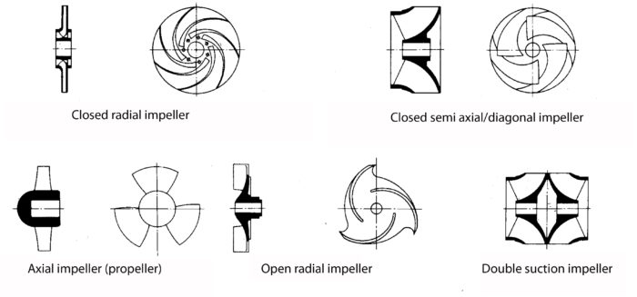
Experience teaches us how the impeller should be shaped in order to obtain the greatest efficiency. The impeller (and often the entire pump) is named according to the flow path through the pump, such as radial impeller, semi-axial impeller and the axial impeller (propeller), see figure 3.2a. There are unlimited numbers of intermediate impeller forms to those shown in order to meet every performance requirement.
Two impellers can be constructed together for parallel operation, double suction impeller, figure 3.2a. For contaminated liquids and where production must be simplified the construction principle of “greatest possible efficiency” is done away with and the impeller has a different shape. A distinction is made in theory between closed, semi-open and open impellers as. well as special shapes for contaminated liquids (see also “non-clogging” pumps).

Figur 3.2a Impellers of different shapes
The right image of the closed radial impeller and semi closed impeller in Figure 3.2a shows the impeller with the front cover plate removed.
Multi stage pumps
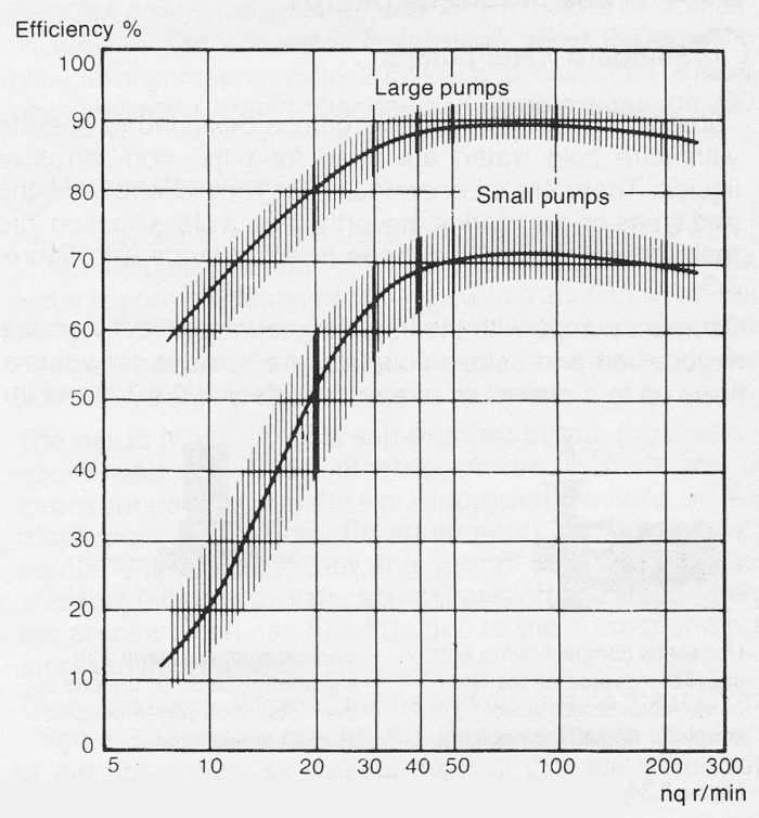
The efficiency of centrifugal pumps is dependent upon the specific speed, figure 3.2b. At Iow specific speeds, the delivery head must be divided up amongst several series coupled impellers so called multi stage pumps, in order to achieve a good efficiency. Every doubling of the number of impellers increases the specific speed by 1,68 (2¾). The following efficiencies, for example, can be read off from figure 3.2b for a small pump:
No. of stages | nq | Efficiency |
1 | 10 | 21 |
2 | 16,8 | 42 |
4 | 28,2 | 63 |
The range of application of multi stage pumps for delivery heads over 50 up to 100 m, is, as a general rule, dependent upon the volume flow and speed.

In addition to classification in accordance with different hydraulic designs, it is practical to apply classification for different areas of application. Within each such area, there are special design features dependent upon
- Iiquid transported
- the driving motor
- the installation
- noise level
- leakage
- operational safety etc.
The following descriptions of the various types is made in accordance with the classifications as shown in figure 3.33. This classification is based upon both technical and marketing considerations and is consequently applied in the following pages on pumps. For this reason different types of pumps have been given numbers in key tables and
product guide.
