
6.2 Electric motor
Electric motor
An electric motor and a pump combined is an energy transformer, where electric energy is transformed to hydraulic energy. The electrical motor will be powered by electric energy, the motor will transform that energy into torque, which is mechanical energy. The torque is used to turn the pump shaft and the pump shaft is connected to the impeller. The impeller transform the torque into the pumped liquid as hydraulic energy, that is, pressure or head.
We are primarily focusing on electric motor issues in ration to pumps or pump motors but in order to understand how they work together, we need to need to start with the basics and that is to understand how an electric motor works.
Electric motors are powered by either Direct Current (DC) or Alternating Current (AC). DC current is the unidirectional flow of an electric charge. A car battery with a plus and minus pole is an example of DC power. That means all electrified pumps in cars runs on DC power.
However, most pumps world wide runs on AC power which is usually supplied to the consumer as 3-phase alternating (a.c.) current with a frequency of 50 Hz, i.e. 50 oscillating periods per second. This frequency is used throughout Europe and most countries in Asia, Africa and south part of South America (south of Brazil and Peru). In the USA, however, the frequency is 60 Hz which is also standard in central America and South America from Brazil and Peru up north.
The most common electrical units are (Unit/Symbol/Designation):
- Current / I / Ampere (A)
- Voltage / V / Volt (V)
- Resistance / R / Ohm (Ω)
- Active power / P / Watt (W) or kilowatt (kW)
- Apparent power / S / Voltampere (VA) or kilovoltampere (kVA)
- Reactive power / Q / Voltampere reactive power (VAr) or (kVAr)
- Power factor / cosφ / (see explanation below)
- Energy / J / Joule or Ws / Watt second, for convenience kWh is usually used to express energy consumption (3.600.000 J = 1kWh)
In a 3-phase supply with system or mains voltage of 415 V a suitable electric motor can be connected to all phase cables. The motor is designated as a 3-phase motor.
Figure 6.2a schematically illustrates a 3-phase system. Between the system voltage Us, also referred to as mains voltage, and the phase voltage Uf, the following relationship applies:
Uf = Us / √3 (√3 = 1,732)

Figure 6.2a 3-phase electric system
System designation 380/220 V (Alternatively 415/240 V)
System voltage Us = 380 V (415 V)
Phase voltage Uf = 220 V (240 V)
Smaller electric motors, up to several kW, are often constructed for connection between a single phase cable and the system’s neutral cable (normal wall socket). These types of motors are designated as single-phase motors.
For the units reviewed as most common earlier, the following relationships apply:
For direct current (DC):
U = I * R Equ. 6.2a
P = U * I Equ. 6.2b
Direct current motors are used for speed regulation of smaller pumps or pumps used in cars, boats, caravans etc.
For single phase AC current:
U = (I * R) / cosφ Equ. 6.2c
P = U * I * cosφ Equ. 6.2d
For 3 – phase AC current:
P = U * I * √3 * cosφ Equ. 6.2e
If the required pump shaft power is Pp in kW and the efficiency of the intended 3-phase motor is ηm then the current requirement in ampere is:
I = (Pp * 1000) / (U * √3 * cosφ * ηm ) Equ. 6.2f
See also calculated pump motor, among the examples in section 12
Active power, apparent power, reactive power and power factor
An electric motor for AC current consumes not only active power, P, which is converted to mechanical work, but also a reactive power, Q, required to build up the necessary magnetic field in the motor. This reactive power does not perform any work and is not converted into heat but is nevertheless a load on the supply grid. Electric power suppliers make a charge therefore for consumed reactive power if it exceeds a certain value.
This relationship is illustrated in figure 6.2b. The active and reactive powers combine to form the apparent power, S. This trigonometrical relationship between P and S constitutes the power factor (pf) cosφ.
The power factor can be determined by measuring an electric motor’s power input, current and voltage at its rated power. The tolerances in this respect are 1-cosφ / 6.
")
For electric motors the power factor usually lies between 0.7 and 0.9. It is lower for small motors, see figure 6.2c. The power factor is dependent upon shaft load, the table in figure 6.2c gives approximate values for the most common types of electric motor for speeds in the region of 1500 r/min.

The amount of pump work determines the power which the electric motor supplies. This means that if a pump in a certain operating situation requires 11 kW then the motor supplies this power irrespective of whether the rated power is 15 or 7.5 kW. This will result in overloading in the case of the 7.5 kW motor, which can cause damage to the motor winding due to overheating. Some form of motor protection device would thus be necessary, whereby, after a certain period of time under overload conditions, the motor is automatically disconnected from the mains supply, causing the pump installation to stop.
A pump motor must, of course, be capable of providing the power which the pump requires. Therefore it’s considered suitable with a safety margin of about 10%, in order to cope with slight unintentional overloading situations which can be difficult to estimate accurately. A motor should not however, be chosen with a too large safety margin since :
- the procurement costs are unnecessarily high
- the efficiency and power factors are lower, and
- starting loads imposed on the mains supply will be unnecessarily high.
Phase compensation
If an installation contains many electric motors, large quantities of reactive power are consumed and the overall power factor is lowered. A solution to this is to install capacitors, which generate reactive power and thereby increase the power factor. This procedure is usually called phase compensation. The capacitors can be applied to motors individually or to groups of motors. Competent calculations for phase compensation must be carried out.
Improvement of the installations power factor does not result in a conservation of energy. It is carried out in order to:
- avoid excess consumption of reactive power involving extra cost
- reduce loads on transformers and electric cables
- maintain voltage potential within the system
Electric motor speed
The speed of an AC electric motor is determined by the frequency of the system and the number of poles in the motor stator to the following relationship:
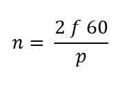
n = speed, r/min
f = frequency, Hz
p = number of poles
From the above it can be seen that a change in frequency causes a change in speed. Electric motors can thus be speed regulated by means of varying the frequency, see further information in sections Variable Speed Electric Motors in 6.1 Pump Motor, 5 Flow regulation and Pump similarity and affinity laws.
In Europe the frequency is 50 Hz, thus the speed of electric motors is 6000 divided by the number of poles. At least two poles are required which produces a speed of
- 2 poles gives 3000 r/min (3600 r/min at 60Hz)
- 4 poles gives 1500 r/min (1800)
- 6 poles gives 1000 r/min (1200)
- 8 poles gives 750 r/min, (900) etc.
Electric motors which are constructed so that they exactly follow the stipulated frequency and number of poles are usually referred to as synchronous motors. For large sizes it is necessary, however, to have a special magnetizing winding, supplied with direct current, together with special starting equipment. This is not necessary for so-called induction motors, which are characterized by the fact that there is a speed differential between the frequency of the system (magnetic field of the stator) and the motor speed. An induction motor thus has a 6-8% lower speed than a corresponding synchronous motor, this slip increases with increased loading. Because of its simple construction the induction motor is most popular for pump operation.
Electric motors for AC current can be equipped to enable the number of poles to be varied in operation, thereby, obtaining changes in speed. Such motors are called pole-changing motors and to a certain extent can be used for speed regulation of pumps.
In most AC motors the rotor is short-circuited and thus has no connection with the stator winding or any external current supply. Such motors are called short-circuited or squirrel-cage motors. In order to limit the starting current and to regulate the speed a variable resistance can be connected to the motor whereby the rotor must be equipped with slip-rings. This type of motor is referred to as a slip-ring or wound-rotor motor.
Electric motor torque
The torque of an electric motor is a measure of the work capacity of its rotor, sometimes it may be necessary to calculate this torque. The following relationship exists between the normal torque, given power and speed:

T = Torque (Nm)
P = Power (kW)
n = speed (r/min)
When starting an electric motor it is necessary to develop a greater torque than for normal operating load, so that the motor can reach operating speed without overheating. Figure 6.2d illustrates a typical induction motor torque curve. When starting, the motor has a relatively high torque, usually 1.5-2 times the torque at the duty point. As speed increases the torque first reduces followed by an increase to maximum torque and finally rapid reduction to the point at which the motor torque is equal to the load torque, equilibrium being reached at the designed duty point.

Electric motor catalogs usually state the starting torque in relation to the normal duty torque and full load current. It should be noted that full grid voltage is assumed. Maximum torque is a measurement of the electric motors momentary overload capacity. This is usually required to be at least 1.6 times the duty point torque, although most electric motors have values which are considerably higher.
Voltage for motors
Generally 3-phase motors, with the exception of pole changing motors, can be used for 380 and 220 V. The motor in this case is marked Y/A 380/220 V and, depending upon the method of connection, can be used for either voltage.
Normally 380 V (415 V) is used for 3-phase motors up to about 200 kW. For larger motors, up to approx. 450 kW or installations with large motor load, higher voltage may be motivated for both technical and economical reasons. According to present international norms for standard voltage (IEC 600038), a system voltage of 660V shall be used. This voltage has the advantage that it enables squirrel cage motors to be constructed for connection to either 660 or 380V since √3 * 380 = 660.
In the case of certain larger motors local voltage increases are often achieved by using block transformers. For motors connected to high voltage systems of 10 or 20 kV (kilovolt 1000V), transformers are normally used for a nominal motor voltage of 3 or 6 kV. Motors larger than 1000 kW can be connected directly to 10 kV systems.
The choice of motor voltage must be made from technical and economical points of view. The determination of voltage involves not only the motor but the complete electrical equipment such as wiring systems, transformer requirements, switch gear, etc.
Generally it can be stated that for larger motor loads it is advantageous to use a higher voltage than 380V (415V).
Torque reduced due to voltage drop
If the grid voltage reduces then the electric motor torque is also reduced, this applies when starting as well as during normal operation. The torque reduces in proportion to the square of the voltage. It is therefore important to ensure that electric cables to the motor are suitably dimensioned so as to avoid excessive potential drop. The maximum acceptable figures usually being 10% when starting and 5% during normal operation.
Starting electric motors
When direct starting a short-circuited (squirrel-cage) motor there is a substantial rush of current from the grid system which results in a potential drop, this affects the motor as well as other equipment connected in the system. Suppliers of electricity therefore lay down certain restrictions in relation to the direct starting of motors, normally direct starting is only permitted for motor sizes of up to a few kW. It is therefore normally necessary to take suitable precautions in order to limit the starting current.
The most usual method for this purpose is the use of Y/D-start (star/delta connection). In principle, this means that when starting, the motor’s winding´s are connected between the phase cables and the neutral cable, Y-connection. These then receive a lower voltage than that for which they are intended, a 3-phase motor for 380V only receives 220 V and the motor develops only a small part of its starting torque, which of course means that the acceleration time is extended. At approximately 80% of normal operating speed the stator winding connections are changed over automatically to the system phase cables, D-connection, which then receives full voltage. Figure 6.2e illustrates the sequence for direct start and Y/D-start respectively for a squirrel cage motor.
 motor")
Figure 6.2e Starting a short-circuited (squirrel-cage) motor
If Y/D-start is to be used, care must be taken to ensure that the start time is not so long as to allow the heat generated by the motor, prior to achieving full speed, to reach damaging proportions. It is also necessary to check that the motor torque will be sufficient to facilitate starting i.e. it must be greater than the load torque. It should also be noted that changing from Y to D causes a substantial torque and current pulse which is greater the nearer the changeover is to maximum torque. For this reason it is desirable to achieve a speed which is as near to maximum speed as possible using the Y-connection.
Y/D starting is often unsuitable for pump motors because of the rapid increase in load torque with speed. If direct start is not possible and if the starting torque is too low when using Y/D starting then a slip-ring motor can be chosen. A starting resistance (rheostat) is connected to the rotor via slip-rings, the principle is shown in figure 6.2f. This resistance facilitates lower starting current and greater starting torque. The resistance is successively reduced as speed increases.
Figure 6.2f Illustration showing the principle of a slip-ring motor with starter resistance

Other methods of limiting the starting current are reactor and transformer starters. Both these methods involve reduction of both starting current and starting torque. It is therefore necessary to check that sufficient starting torque is available. It is only in exceptional cases that these methods are used for pumping applications.
For further reference to starting apparatus see section about soft starters and frequency inverters.
Electric motor efficiency
Electric motors are designed to run at 75% of rated load where the motor efficiency usually peak. Losses in motors consist of bearing and friction losses together with different losses related to electro mechanical losses.The recommended load to avoid electro mechanical losses should be between 50% to 100% of rated load since the motor efficiency tends to decrease dramatically below about 50% load. Overloaded motors on the other hand, tend to overheat and lose efficiency. Electric motors are in general designed with a service factor that allows occasional overloading. If the service factor is too large the motor risk running below peak efficiency most of the time. If motors needs to be over sized because they must accommodate peak conditions, such as when a pumping system must satisfy occasionally high demands. Try to implement methods to meet variable load conditions, such as two-speed motors, adjustable speed drives or other load management strategies that maintain loads within an acceptable range.

Figure 6.2g schematically shows speed, efficiency, factor and current consumption of an electric motor. From the figure it can be seen that efficiency varies with motor load.
Standard IEC 60034-30 is built on efficiency classes starting from IE1, followed by IE2 (more efficient than IE1), IE3 and so on with efficiency of the next series better than the previous. The old system which was replaced in 2008 was based on a reversed logic where Eff1 was more efficient than Eff2. This system was terminated since it didn’t motivate manufacturers to compete for better efficiency the Eff1 was already the best. Eff1 corresponds to IE2 (Eff2 with IE1) which means IE3 was already more efficient than Eff1, now, we have both IE4 and IE5 motors on the market.
In the old days, the efficiency of medium sized electric motors (10-100kW) was usually 85-90% at rated load. Better values could be obtained for larger motors, whilst 75-85% was usual for smaller motors. As seen in figure 6.2h the development has been good, especially for the larger sizes.

Noise from electric motors
The quiet running of electric motors is becoming increasingly important and special requirements can be made in this respect. However, the noise level requirements of the motor should not be more stringent than tor other components, which often generate quite high noise levels.
For the quiet operation of an electric motor powered pump unit it may be necessary to select a low noise level motor. In such circumstances, however, it may be advantageous to choose a cheaper standard motor and mount the unit on vibration dampers and surround it with sound deadening shields instead.
Noise from motors is generated by the cooling system, by the bearings and brushes and also by the magnetic circuit. The dominant source of noise depends upon the size of the motor, speed and type of coupling as well as the design and construction of the motor. Bearing and magnetic noise are caused by vibration in the motor and can be transmitted through the mounting framework to other locations.
Maintenance of electric motors
An electric motor for a pump requires regular service, as does the pump itself, in order to give good performance. The basic prerequisites for long service life of an electric motor are, apart from selecting the correct motor, careful alignment and mounting. Regular balancing checks to prevent out-of-balance running should also be made. Vibration can be caused by faulty bearings, faulty winding´s or irregular air gaps and also by out-of-balance of the couplings.
Most electric motors use roller or ball bearings and it is important to ensure that they are correctly lubricated. The service intervals between lubrication depends upon the type of bearing and the environment in which it operates. Lubrication instructions should be obtained from the supplier and followed carefully. Removal of bearings for inspection should be avoided whenever possible since they can be damaged when pulling and reassembling. Checks should also be made by listening to bearing noise and observing the lubricant.