3.2.8 Groundwater pumps and sump pumps
Groundwater pumps and sump pumps
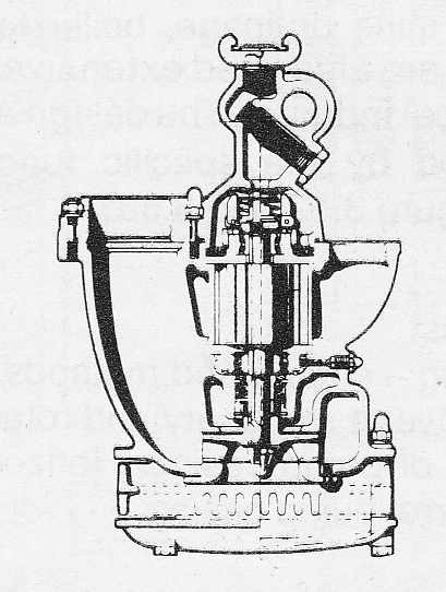
Groundwater pumps and sump pumps are pumps placed in ditches, so called sumps. They are often used to drain building foundations which are deeper than the sewage system. Figure 3.281a shows two different designs. In the case of the smaller sizes, submersible pump units are used and in the case of the larger sizes, the pump is immersed and the motor is dry placed.
Groundwater pumps are set up for automatic operation with start-stop controlled by level monitors, which normally consist of level arms, placed in the pump sump. Two pumps are normally used with the other pump as reserve and for back-up purposes. In the case of corrosive ground water, a pump of cast iron is used otherwise die-cast light metal is normally used for the smaller pumps.

Figure 3.281a Groundwater pumps. The left-hand illustration shows a submersible type. The right-hand illustration has the pump immersed and the motor dry placed.
Electrically driven sump pumps
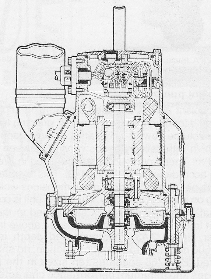
Electrically driven construction sump pumps are submersible pumps connected directly to a motor and comprise, together with automatic control equipment, a complete unit. Their weight is the Iowest possible due to the use of light metal alloys although their resistance to corrosion is Iow. The parts which are exposed to wear from the liquid are on the other hand, of high quality. Typical features are hard metal impeller, rubberized wear parts around the impeller and hard-faced seals. The electric motor is completely encapsulated and cooled by the pumped fluid through a double jacket. In order to protect the motor in the case of blockage or operation without fluid, the motor is provided With a specially built-in motor protection unit. Normally the motor windings have built-in thermo contacts which stop the motor when the temperature is too high by means of an inbuilt contactor. The Shaft seal is nearly always of a double type With an intermediate oil chamber figure 3.281b. Normally construction pumps have suction strainers which limit the particle size to 5-10 mm, but there are special models With a through flow of up to approximately 100 mm for pumping sludge and mud.

Figure 3.281b Submersible Construction sump pump
Construction sump pumps are used for draining all types of building sites from the smallest ditch or hole to the large projects such as tunneling in mountains or harbour building. This type of pump is practical in the event of flooding and for all other temporary pumping requirements. Of particular convenience is the fact that pump companies in this field offer both small and large pumps for hire for periods ranging from one day to several months.
Combustion and Compressed air driven
When electric power is not available, on building sites for example, other sources of power must be ermployed, such as combustion engines, compressed air from mobile diesel sets or hydraulically from a separate set or one which is built into a vehicie. This type of pump is also suitable for intermittent use in construction work such as road making, rock blasting and excavating or as a fire precaution when carrying out controlled burning.
Combustion engine driven sump pumps
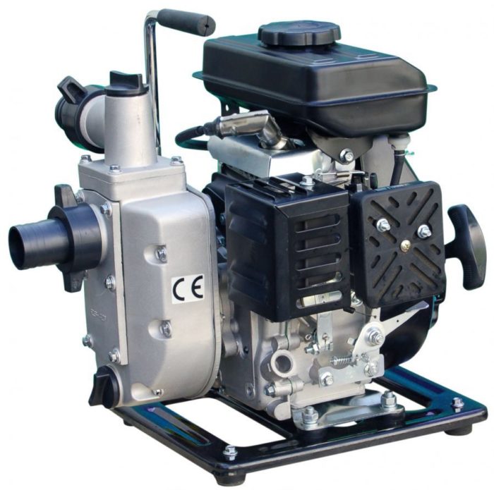
Combustion engine driven sump pumps are usually self-priming centrifugal pumps, see figure 3.48. In order to be self-priming the pump must be filled with fluid prior to starting. The evacuation times quoted usually refer to the time taken to obtain the full pressure head at the pump for a specific suction head, using a hose having the same diameter as the pump’s suction connection and whose Iength exceeds the suction head by two meters. The pump performance can be adapted to actual requirements by varying the engine speed.

Figure 3.281c Combustion engine driven sump pump
A centrifugal pump becomes self-priming if the suction connection is located above the center of the pump shaft and if the pump casing is shaped so that any gas or air bubbles become completely surrounded by liquid and are pumped from the suction to the delivery side. Since there is only a limited amount of fluid during evacuation the gas and liquid must be separated, whereupon the liquid is returned to the suction side to continue gas pumping.
The internal design and shape of the pump casing to achieve this effect varies considerably depending on the manufacturer. When choosing a pump it is important to take into account the wearing effect which sand, for example, may have upon the pumps evacuating capabilities. Combustion engine driven pumps can handle solid particles of up to 10-15 mm. The suction hose is reinforced because of the vacuum caused by pumping. The normal suction strainer can usually be replaced with a so called dry suction plate, in order to facilitate pumping down to within a few mm of a floor. The pump should be equipped With a protective safety frame and runners or skids to enable it to stand on soft ground.
Combustion engines are available With Shaft outputs of up to approx. 2 kW for two stroke petrol engines and up to approx. 10 kW for four-stroke engines. Diesel engines are used from about 4 kW. Engines are normally noise insulated to 75 dBA measured at a distance of 1.5 metres. To achieve this level of noise it is usually necessary to fit silencers to both the inlet and exhaust sides. The engines are normally splash lubricated which means that the pump must be placed on a relatively flat surface, the inclination may seldom exceed 20°.
Compressed air driven centrifugal sump pumps are similarly designed to those which are electrically driven. They are thus submersible and equipped with or without special heavy duty components for pumping contaminated water. The compressed air motor can comprise of a high speed commutator motor lubricated by oil mist lubrication, figure 3.281d.

Figure 3.281 Compressed air driven centrifugal pump
