
9.6 Parallel pump operation
Parallel pump operation
For parallel pump operation, two or more pumps are connected in parallel. The resultant Q-H curve for pumps operated in parallel is obtained by adding the actual volume flows for each pump at the system head at a specific flow.

Figure 9.6a Parallel connected pumps.
Parallel connection of pumps is used for the purpose of achieving large flows and for dealing with greatly varying flows by operating a varying number of pumps. The yield of parallel connection is dependent largely upon the shape of the system curve.

Figure 9.6b Parallel connection of two similar pumps with different system curves.
For steep, friction dominated, system curves only an insignificant increase in volume flow is achieved by parallel pump connection. A much better yield is obtained if the system curve is dominated by static head. The pump’s specification data (Q and H) is based upon the pump’s nominal duty point (B in figure 9.6b). If only one pump operates, the duty point will then be at point A. This can cause conditions where there is risk of cavitation (because of the poorer NPSH-value at point A than at B) and risk for overloading of the motor.
The resultant efficiency curve for the “package” is calculated from the relationship.
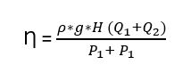
For two similar pumps the efficiency values are the same for each separate pump except that the Q values are displaced towards double values of Q-figure 9.6a.
Unstable pump curves should be avoided when pumping in parallel. In any case the intended operational range should not fall within the unstable region without taking special precautions.
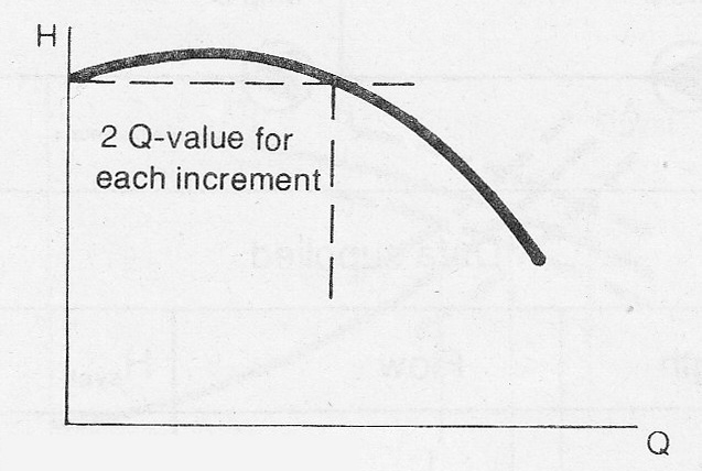
Figure 9.6c Unstable pump curve
The problems which can occur are, for example, irregular flow due to varying operational points and the inability of a pump to open its non-return valve when starting.