
1.5 Pipe system for pump
Pipe system for pump
The pipe system for pump should be designed so that the pump unit can be dismantled without involving extensive work on the pipes. This may mean that displaceable couplings and short sections may have to be incorporated in the pipe. It should be observed that it is very difficult to fit in a pipe section with flanges as well as gaskets unless it is possible to displace neighbouring sections of pipe. The need for flexible joints to compensate for uneven loads and expansion joints to accommodate expansion of the pipe in the event of changes in temperature must also be borne in mind.
Necessary supports and mountings for the pipe system must also be provided. Considerable forces are released by line shock (water hammer) in the case of valve operation or during the starting and stopping of pumps. Figure 1.5a illustrates an example of normal mounting requirements of pipes adjacent to a pump. Strong bands around the pipe should be provided at the mounting points.
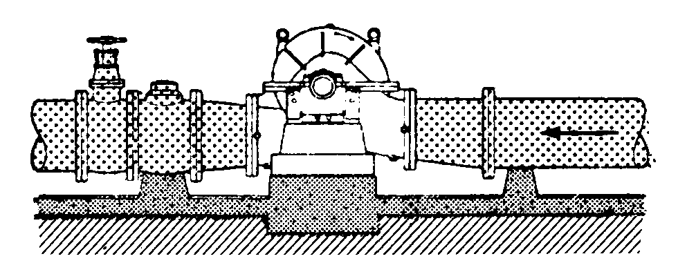
Figure 1.5a Correct mounting of suction and delivery pipes.
When connecting pipes to the pump, care must be taken to ensure that stresses in the pump casing are not caused by flange deflection. Stresses of this kind can cause cracks in the pump casing and galling between the impeller and sealing rings.
If a centrifugal pump is at times driven at greatly reduced flow, this may cause a rise in temperature which may even involve vapourisation of the pumped liquid. To prevent this, it may be necessary to incorporate a return pipe from the delivery pipe to the pump sump, this pipe being fitted with a throttle plate or, better still, a control valve which permit adequate return flow.
The pump suction pipe should be designed to rise evenly with few bends and preferably no valve. If a valve must be incorporated, it should be of suitable type.
The suction pipe should be designed to be entirely leak tight and to prevent formation of air pockets, see figure 1.5b. If the pump is located lower than the lowest level in the pump sump and thus has a certain supply pressure, the inlet pipe system for pump should be designed to fall evenly so that the formation of air is avoided.
Examples of correctly and incorrectly suction pipes for pumps

Figure 1.5b Correct routing of suction pipe
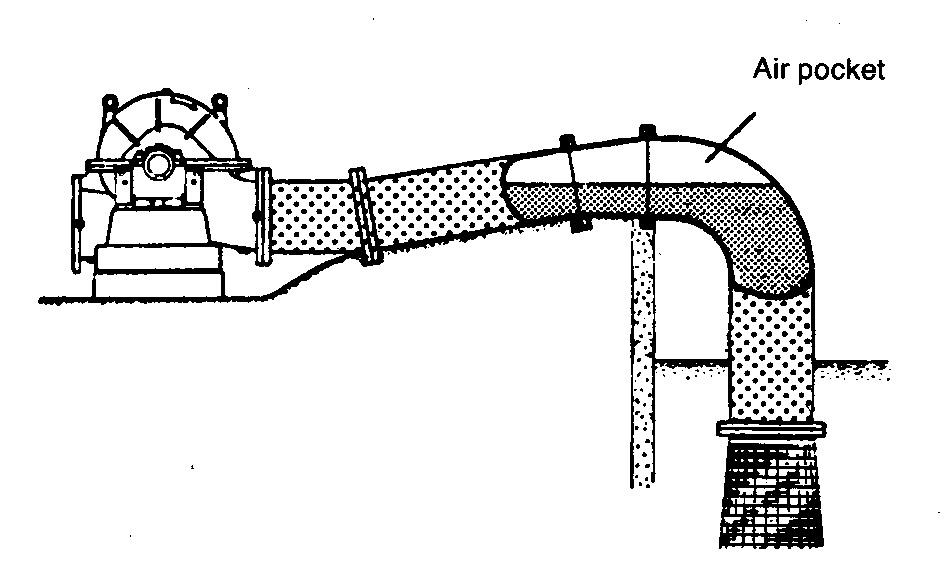
Figure 1.5c Incorrect routing of suction pipe
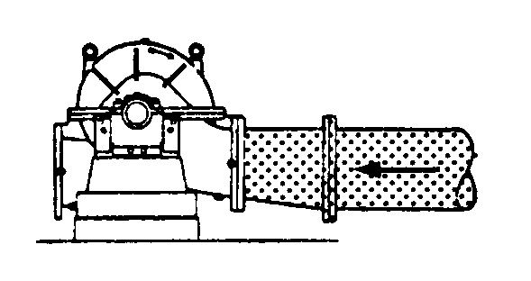
Figure 1.5d Correct installation with eccentric taper pipe
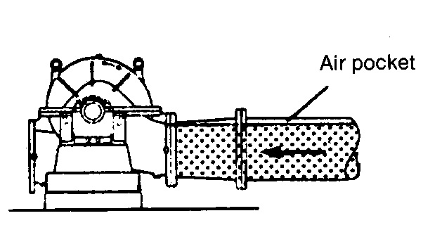
Figure 1.5e Formation of air pocket due to concentric taper pipe
Whenever possible, bends should not be connected directly to the suction side of the pump. This can lead to uneven loads which can result in both a deterioration in performance as well as abnormal axial loads. Figure 1.56 shows a suitable design in this respect
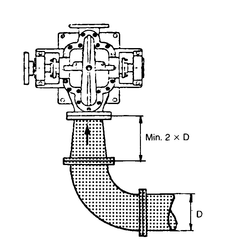
Figure 1.5f No bends connected directly to pump suction
Make sure to follow local regulations and standards for pipe works. Pipe systems to public (municipal) water supply and sewage pipes shall be designed in accordance with the water supply and sewage building standards prescribed. In the cases of places of employment to which the provisions of the Public Health and Factory Acts apply (these also cover water supply and sewage disposal, heating, ventilation and sanitation as well as district heating plants) or to such places as are used under conditions where supervision is called for according to regulations governing safety or commodities which are harmful to the environment or to health or which are inflammable, pipework shall be designed in accordance with the standards for pressure piping systems.
The requirements associated with the piping standards can possibly be supplemented by special provisions for certain processing industries (Classification societies in the case of marine applications). The piping standards define design pressure and temperature, maximum permissible design stress, materials and thickness etc. to comply with test pressures, and specify jointing standards, flanges etc. together with other design requirements such as expansion allowance, flexibility, drainage and ventilation.
Auxiliary equipment such as pipework supports etc. are also dealt with. Construction and installation are specified with regard to manipulation, heat treatment, standards of workmanship, cleanliness,vtesting and inspection. There are special standards relating to welding, preparation, carrying out, testing and requirements. For pipes carrying fluids which are dangerous, toxic, inflammable or otherwise harmful to the
environment, the standards prescribe codings and warning signs etc.
The basic regulations for safety and control with respect to pressure vessels, pipes etc, are to be found in the relevant statuary safety and industrial regulations. There, for example, it is stipulated that a pipe with its auxiliary equipment and fittings shall, with regard to material, strength and design, maintain a high degree of safety and be connected up in a suitable manner. Factory Inspectorate draw up rules for inspection and control and ensure that the provisions of the relevant legislation are complied with in practice.
Normally inspection and testing of pipe system for pump is carried out by and is the responsibility of the manufacturer who may or may not be required by the purchaser to provide test certificates. The purchaser or his representative may also wish to witness such tests. Tests or inspections may be required to be performed by or in the presence of Inspection Authorities connected with or central government departments.
It is obviously of the utmost importance that all tests and inspections are properly carried out in order that the component, sub-systems and ultimately the complete plant shall be rendered safe. The necessary insulation of pipes as protection against heat losses, fire damage, condensation, etc. must be provided.
Technical expertise should, however, be sought for this purpose. The marking of pipes to indicate the medium transported as well as direction of flow and pipe material.
It may sometimes be necessary to study a pipe system with respect to noise. The transmission of vibrations via pipes can be reduced if part of the pipe is replaced by a vibration absorbing expansion bellows of flexible material. This measure is jn any case necessary for every pump resting on a flexible sound-suppressing base, since the pump unit in such cases is subject to movement and should not therefore
be rigidly connected to the pipes. Bellows have a limited capacity to suppress sound or vibrations conducted by the liquid conveyed through the bellows. On the other hand 90° pipe bends exercise a greatly superior suppressing effect.