6 Pump drives
Pump drives
A pump requires external energy, this is supplied by pump drives. It is usual to employ a separate electrical motor directly connected by means of a suitable coupling. This is the simplest solution and gives the smallest loss and is always applied when the pump and motor speeds are the same. If the speeds of the motor and the pump must be different or if the motion is reciprocating, as in the case of piston pumps, the transmission of energy
becomes more complicated, involving the application of gears, converters or belt drives. Pump driving machines can be water or steam turbines, hydraulic or compressed air systems, combustion engines or electric motors. Relatively large numbers of pump types for intermittent use at construction sites, etc., drainage pumps for example, are equipped for use with some kind of combustion engine. But many of the above mentioned pump driving devices are special cases. Electric motors are, however, completely dominant when ever pump drives are considered. The ease of use, the compact but yet powerful source of energy, the relatively low cost and the ability to control are main advantages. Pump drives with electric motors will be most extensively evaluated and described means of pump drive here and every where else in pump related handbooks etc.

When talking about electrical motors, we are often referring to AC Induction motors, also called asynchronous electrical motors. Synchronous electrical motors are expensive compared to asynchronous electrical motors since they require initial DC power, slip ring and brushes. They are both normally two pole or four pole motors where a 2 pole motor speed is close to 3000 rpm and a 4 pole 1500 if driven in a 50Hz grid. If the same motor is connected in a 60Hz grid, the speed is 20 percent higher.
The speed of a synchronous electrical motor = ( 120 * f ) / P
Speed = rpm
f = frequency in Hz
P= Number of poles
Now, the 1500 or 3000 rpm respectively is the synchronous speed but since asynchronous electrical motors have slip, slip means the rotor is rotating a bit slower than the magnetic field, the rotational speed is a bit lower. There is no exact science here but motor suppliers will give the information in table format, however, it is normally 2-5% lower speed than the synchronous speed, as a rule of thumb, better efficiency means less slip.
Centrifugal pumps have a pump curve with indication of best efficiency point (BEP) at a certain flow and head. The pump curve is only valid at a specific motor speed. If the system, in which the pump is supposed to operate, requires another flow or head, the pump needs to be controlled. The most efficient way to do that is to control pump speed. If the speed is increased, the flow and head will increase and the opposite if the speed is decreased. The curvature of the pump curve will look the same but the performance will be different, that means we can adjust the pump speed so that the BEP will be optimal at our duty point. The relationship between speed, flow, head and efficiency is explained in the Affinity Law pages.
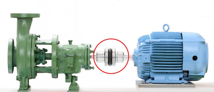
The pump and motor shafts are connected with a shaft coupling. The coupling transmit torque from the driving shaft to the driven shaft and allows for certain axial and radial movement between the shafts. There are different types of shaft couplings defendant on torque transmitted, axial or radial load, size, type of pump, environment, load chocks, speed and ability to absorb misalignment.
The pages about couplings intend to present the factors which influence the relationship between shaft couplings and the pump unit. Beginning with a short review of the different types of coupling and an explanation of the various types of misalignment and the forces and moments which are transmitted. One section gives advice on service factors for couplings with special emphasis on the torque loads when starting electric motors.
Pump shaft alignment is considered to be of importance, several different methods are explained here with the intention of making alignment quicker, cheaper and better. There is also a section Choice of shaft coupling, describing the shaft coupling selection process and it contains a checklist with important factors related to shaft coupling selection.
