
1.3 Pump foundation
Pump foundation
The recommended conventional pump foundation consist of a metallic base-plate anchored to a concrete floor secured with epoxy grout. Improperly designed pump foundations leads to misaligned machines, high vibration levels and eventually premature pump failures and increased maintenance costs. Maintenance issues due to poor pump baseplate foundations are alignment and vibrations causing bearings, seals and couplings to premature failures, thus the pump foundation is an important factor for pump life cycle cost (LCC) with the exception of pumps directly incorporated into the piping, as well as submersible pumps and builders drainage pumps who doesn’t require a foundation.
Horizontal pumps are usually supplied with pump and motor mounted on a common base plate of cast iron or frame construction, tested and aligned. Large pumps are generally supplied with a separate motor. Alignment in such cases requires more extensive work and must be performed on the foundation.
Vertical pumps with attached motors are supplied with a base or mounting plate, tested and aligned. In the dimensioning of pump foundation, regard must be paid to the relationship between the height of the pump and the surface of the base or mounting plate as well as to the torsional moment of the pump unit. If the pump unit is divided, for example, so that the electric motor can be mounted above an overflow level, separate foundations must be designed for both the motor and the pump. It should be noted that alignment should always be checked after installation prior to start up.
The purpose of the foundation is that, by virtue of its mass, it is capable of counteracting vibrations and absorbing external loads such as hydraulic loads and tightening forces from pipes as well as to preserve the pump-motor alignment. If low noise-level demands are imposed, the foundation may have to be of a special vibration suppressing design. A strong foundation and grouting can result in a unit that gives reliable, uninterrupted service versus one that requires constant realignment. It should be everyone’s concern that only the best materials, together with proper design, be used when installing the pump.
For smaller pumps the foundation may be of concrete or designed as a steel structure, there are also alternative designs available such as polymer concrete baseplates, polymer concrete foundations and pre-grouted metallic baseplates. In the case of large pumps thorough strength of materials calculations must usually be carried out. The design and dimensions are executed in accordance with the pump supplier’s measurement drawings and other information.
To the foundation bolt center line dimensions adequate space should be added for their fastening. If the type of pump in question requires free space in the axial direction beyond the shaft journal at the driving end, this dimension is also added. It is also necessary to properly connect the pump to the system by accurately aligning it to the piping system, as well as the driving motor. The foundation should be sufficiently high to facilitate the connection of pipes and to ensure adequate space for drainage devices, if any, and that there is space for the fitting, alignment and maintenance of the pump, motor, valves, packing, strainers and filters in the connection pipes.
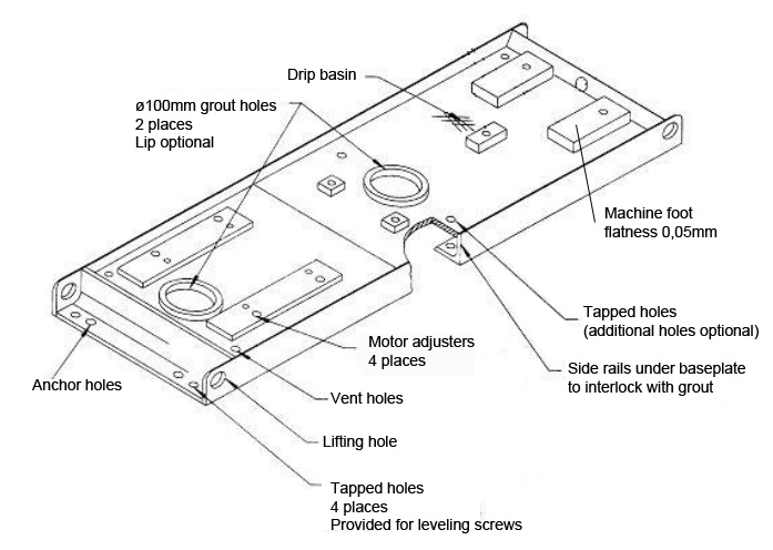
Recommendation is that baseplates shall be provided with at least one grout hole having a clear area of at least 125 cm² (19 in²) and no dimension less than 75 mm (3 in) in each bulkhead section. Holes shall be located to permit filling the entire cavity under the baseplate without creating air pockets. The holes shall preferably be accessible for grouting with the pump and driver installed on the baseplate. Grout holes in the drip pan area shall have 13 mm (0,5 in) raised lip edges. If the holes are located in an area where liquids could impinge on the exposed grout, metallic covers with a minimum thickness of 1,5 mm (0,06 in, 16 gauge) shall be provided. Vent holes at least 13 mm (0,5 in) in diameter shall be provided at the highest point in each bulkhead section of the baseplate.
Epoxy grout, primer and concrete compatibility
There are a number of issues identified causing premature pump failure. One of them being alignment. With metallic baseplate and concrete grout designs it is common that voids develop as a result of corrosion. The void cause a separation between the baseplate and concrete, this result in reduced stiffness, increasing vibration levels and misalignment. This is a chain of factors contributing to reduced pump LCC and one major contributing factor why users nowadays specify epoxy grout as a standard in many industries.
However, epoxy grout designs have weaknesses and special attention must be addressed to primer and epoxy grout compatibility. Will the primer used on the baseplate work with the grout. Most industries tend to standardize the supplier of grout but the primer used for the baseplate depend on the pump manufacturers supplier of primer. Many experts has tried to find generic recommendations, e.g. when forming the API standard 8th edition in 1995, there was a discussion whether the user should specify what primer to use but the pump manufacturers claimed that might violate environment permits, the conclusion at that time was that zinc silicate primers were compatible with all epoxy grouts. The recommendation was not received with enthusiasm and was removed from the 9th edition 2003. The conclusion must be to always check chemical compatibility with the suppliers.
Another issue is if the baseplate is clean enough after transportation. Is it enough to wipe it clean with a cloth? Remove the dirt with soap and water or even an epoxy compatible solvent? Actually, if a baseplate and epoxy grout pump installation should be applied with full strength, the grout should be applied to baseplate clean bare metal. That means the baseplate should be sandblasted to ISO 8501 Grade Sa2, which means the machines must be removed from the baseplate and the baseplate sandblasted immediately prior to installation, leveling and grouting. Even in dry environmental conditions, the risk of rust blush appearing on the baseplate before grouting is imminent. In tropic or sub tropic climate humid conditions, it is more or less inevitable.
Leveling and flatness
Prior to filling epoxy grout the base plate needs to be leveled. If the pump comes assembled on the base plate, the pump (and other equipment such as a motor) needs to be removed from the base plate. Leveling is done using a laser, optical tools or a machinist’s precision level. The base plate is adjusted to level with the anchor bolts and leveling screws which was previously installed when the concrete foundation was being poured. The rule of thumb is that base plate should be leveled better than or within 0,5° deviation, which equals 8,7 mm/m.
According to API610 which can be consider as a strict guideline, the pads shall be fully machined flat and parallel. Corresponding surfaces shall be in the same plane within 150 µm/m (0,002 in/ft) of distance between the pads. If specified, this requirement shall be demonstrated in the pump vendor’s shop prior to mounting of the equipment and with the baseplate supported and clamped at the foundation bolt holes only.
Flatness of base plate pads should be within 0,05 mm (0,002 in) to avoid soft foot problem.