6.1 Pump motor
Pump motor
Selecting a suitable pump motor for a simple pump installation may look like a straight forward task but it requires a specification. On a basic level, the motor needs to be able to run on the local grid. Larger industrial sites might deviate from the local grid specification due to own power or transformator specifics. A basic specification needs to include number of phases (one or three), voltage and power drawn at nominal and maximum load, if the pump motor is supposed to operate on a foreign market we have to specify frequency (50/60Hz) and make sure our installation follows local regulations on safety and other standards.
In addition to the basic specification we have to consider ambient conditions like temperature, dust, water or humidity, mechanical installation issues like mounting (e.g. flange or foot), electrical installation details (e.g. terminal box, frequency inverter, instrumentation etc.). The motor needs to be specified with regards to acceptable noise level, overload protection, efficiency class, number of starts and stops per hour etc.
There are a large number of different pump motor alternatives and in addition to the above requirements we need to understand the pump load which is specified in the Pump section of this handbook.
There are a number of standard motors available and the essence of our specification will point towards the most suitable pump motor alternative for our pump and its application. The following are the most common types of electrical pump motor used for pump operation.
Constant speed AC motors
- Synchronous motor
- Induction motor, short-circuited (squirrel-cage)
- single phase
- 3-phase
- submersible
- wet/wet rotor
- magnet motor
- Induction motor, slip-ring type
Variable speed AC motors
- Induction motor, slip-ring type
- Pole changing motor
- Commutator motor
- Motors with special controls
DC motors
AC motors constant speed
Synchronous pump motors is characterized by the fact that speed is totally dependent upon the frequency of the electric current supply and the number of poles, see section about Electric motor speed. The motor thus runs at constant speed irrespective of load.
The synchronous motor must be fitted with a special starter winding, which is disconnected during operation. Also necessary is a d.c. energized magnetic winding, the d.c. current being supplied by a generator in the motor. The reactive power can be regulated by means of varying the magnetization. A synchronous motor can, therefore, contribute to an increase of the power factor W in an installation.
For pump operation synchronous motors are normally used in larger sizes and in cases where there are special requirements. The reason being that this type of motor is relatively and sensitive to variations in the grid network.
Cage (short circuited) induction motors
Induction motors are constructed on the principle that a speed differential shall exist between the rotating stator winding field and its rotor, thereby maintaining induction in the motor in a simple and reliable manner. The speed of an induction motor is therefore somewhat less than for a corresponding synchronous motor with the same number of poles (see Section), the relative slip (s) is:
s = (ns – n) / ns
ns =synchronous speed r/min
n = induced speed r/min
The speed of an induction motor reduces with increased load, see the relationship between torque, power and speed in section Electric motor torque.
Single phase cage induction motors are used for smaller pumps with power requirements up to several kW, for example, barrel pumps which need to be portable and be fed from wall sockets. The direction of rotation can be changed by means of simple switching.
Single phase motors produce no torque when starting and require an auxiliary winding to facilitate starting. The following categories of motors are supplied:
- With resistance starter winding, which is disconnected after starting.
- With auxiliary winding in conjunction with separate attached capacitor. For low starting torque requirements, the capacitor can be connected during operation, whilst for larger starting torque requirements the capacitor must be disconnected after start. Other combinations are necessary to achieve optimum conditions for large starting torques and good maximum performance.
- As commutator, so-called universal current motor.
Three-phase cage induction motors are the dominating type for pump operation. The construction is simple, requiring a minimum of maintenance and spare parts, Their starting qualities are generally good. There are usually two types of rotor to choose between: simplex and double cage. The former is used for direct starting if the starting torque does not need to be high. The simplex rotor is the most common and is especially suited when frequent momentary overloading occurs.
Motors for submersible pumps are usually 3-phase motors. Although single phase motors are not unknown for this purpose.
Motors for pumps in boreholes and similarly limited spaces usually have water lubricated bearings. Cooling is achieved by utilising the pumped fluid. The rotor chamber is filled with water and protected against freezing. The motor is connected to the pump by means of an intermediate section, which also serves as the pump inlet. Because of the limited space both the pump and motor must be specially designed.
Motors for pumps immersed in larger vessels can be connected directly to the pump casing. Shaft sealing is by means of two mechanical seals in an oil bath. The motor is normally cooled by means of the pumped fluid, which is effective and requires less motor power than for an equivalent air-cooled motor. The motor should be fitted with temperature sensors (thermistors) for 120°C, integrated in the stator winding so as to protect against dry running. The temperature sensors control a contactor which can be incorporated in the connection housing. The following cooling systems are utilised.
- Direct cooling of the motor outer casing, which can be corrugated to increase the surface area, is used when the motor is permanently immersed in liquid which does not exceed 40°C.
- Casing cooling using the pumped liquid. Part or all of the process liquid passes between the outer casing and the motor casing. The pump can be either wet or dry installed, although dry-running is not permitted. At part-flow-cooling the liquid must not contain solid particles. The temperature of the liquid must not exceed 40°C.
- Oil cooling. Oil from the pump’s oil case is circulated in the outer casing during operation.
- Casing cooling using external liquid which passes between the outer casing and the motor casing. Temperature of the pumped liquid can normally be up to 70°C. This system is used in potentially explosive atmospheres. The motor should stop in the absence of positive pressure.
A so-called wet motor consists of a 3-phase or single phase cage induction motor, hermetically attached to the pump casing. The pump impeller is connected directly to the electric motor shaft. The rotor and bearing in the motor are lubricated and cooled by the pumped liquid. This construction constitutes a leak-free (glandless) pump suitable for transportation of hazardous fluids and for use in potentially explosive atmospheres.
In the case of a wet motor the pumped fluid completely fills the motor chamber. Both the stator and the rotor are immersed in the fluid. For wet rotor motors the stator winding is kept dry by means of a thin stainless steel tube which separates the stator from the fluid. This type of construction is used for particularly troublesome media.
Wet motors and wet rotor motors are also used for submersible pumps.
A magnetic motor is a 3-phase or single phase cage motor where the motor shaft-end is fitted with an internal magnetic ring. The pump shaft is fitted with a corresponding ring and a non-rotating sleeve between the two rings attached to the pump casing. This construction also permits a leak-free pump.
Slip-ring induction motor
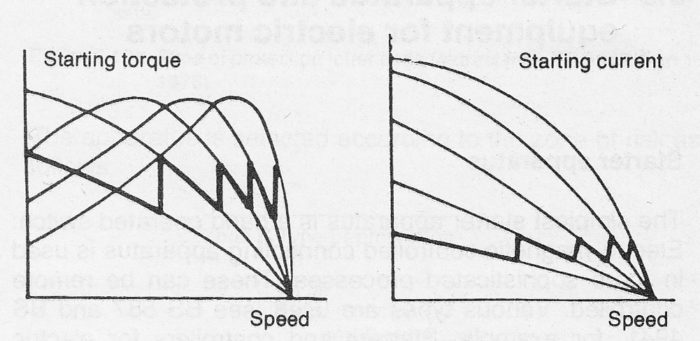
In this type of motor the rotor windings are connected to slip-rings. By connecting them to a power consuming resistance during starting, considerable limitation of the starting current can be achieved. The resistance can be adapted to suit the desired starting torque. During starting the resistance can be successively reduced as required as speed increases, this can be arranged as an automatic function. The resistance is completely disconnected at full load
speed. Figure 6.1a schematically illustrates the connection of a starter resistance and figure 6.1b shows the starting sequence of a slip-ring motor with five resistance steps.

Figure 6.1a Slip-ring induction motor with starting resistance

Figure 6.1b Starting sequence of a slip-ring motor
The connection of starting resistance to the rotor winding is via brushes in the slip-ring device. To reduce wear of the slip-rings and brushes it is usually arranged so that the brushes are lifted from the slip-rings when full load speed iis achieved.
Slip-ring motors are used when there is a requirement for low starting current and in cases where the starting torque is relatively high. This type of motor can also be used when speed-regulation of the pump is required, see the variable speed electric motors below.
Variable speed electric motors
In the section about Flow regulation, speed regulation of pump motors is dealt with in more detail. For this reason, only the pole-changing electric motors are dealt with below.
Reference for variable speed motors are otherwise made to Flow regulation section.
By using pole-changing motors (see section about Electric motor speed) stepped speed-regulation can be be achieved. For pump operation it is common to use two-speed motors whereby the combination of pole numbers determines the speed. The combination 2/4 gives speeds of 3000/1500 r/min, the combination 2/8 gives 3000/750 r/min. (somewhat less for induction motors). Lower efficiencies are normally expected at low speeds.
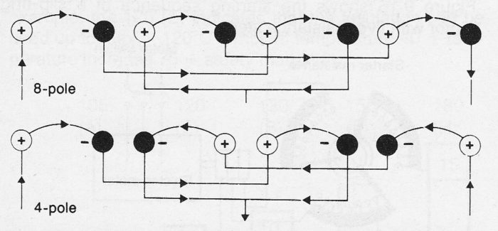
For the usual type of two-speed motor the stator is fitted with separate motor winding for each set of poles. The output of the motor will thus be relatively low when only half of the stator capacity is used for each set of poles. The same winding can, however, be used for both sets of poles by means of a special connection method (Lindström-Dahlander-connection), see figure 6.1c. Pump motors with this type of winding cannot be Y/D started.
Two-speed motors are normally constructed as cage electric motors. Start can be achieved at either the low or high speed. In the latter case, however, it does not always follow that the starting current will be correspondingly lowered.

Figure 6.1c Principle of pole-changing stator winding for two-speed motors.
