6.12 Pump motor mounting
Pump motor mounting
There are many different ways a motor can be installed and selecting proper pump motor mounting is essentially about reliable operation, efficient performance and pump motor life time. The design of electric motors with respect to bearings, shaft and methods of attachment is covered by IEC 60034-7 and NEMA Standard.
IEC (International Electrotechnical Commission) is the world’s leading organization for the preparation and publication of International Standards for all electrical, electronic and related technologies. The IEC is one of three global sister organizations (IEC, ISO, ITU) that develop International Standards for the world.
The National Electrical Manufacturers Association (NEMA) is recognized as electrical standard the US and publishes more than 700 electrical Standards and technical papers. NEMA represents the collective interests of America’s electrical manufacturers at every level of government, including local building codes, infrastructure funding, national energy laws, and international trade.
The motor construction allows for operation in all mounting positions, a motor which is normally intended for a particular mounting position is also shown in alternative positions, most motors is such that they can usually be operated in many mounting positions. However, some mounting positions require additional construction modifications to achieve optimal performance.
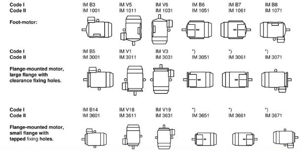
Figure 6.12a shows examples of various types of IEC 34-7 mounting arrangement of electrical motors together with their international designations. For practical reasons larger manufacturers of electric motors often have their own methods of designation (disposition numbers) for standardized motors.

Junction box
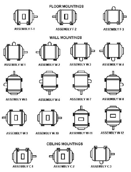
The standard IEC mounting position places the junction box on the top of the motor, known as the IM B3 mounting position in IEC frame (see figure 6.12a) which corresponds to F3 in NEMA frames standard pump motor mounting. The NEMA standard mounting position, on the other hand, is referred to as F1 (see figure 6.12b) with the junction or conduit box located on the left side of the motor facing the output shaft. The NEMA standard mounting position is F1, is the most popular configuration, and is the standard for the majority of motors sold on the US marketplace.

Terminal markings and direction of rotation
These are covered by IEC 60034-8, which determines terminal markings, direction of rotation and relation between terminal markings and direction of rotation for AC machines without commutator and DC commutator machines.
According to these standards the phases in a 3-phase motor shall be designated by the letters U, V, W and the outer neutral connection shall be designated by the letter N. The normal direction of rotation in electric motors is clockwise, viewed on the shaft drive end, for phase sequence U, V, W.
Rated power, size and connection dimensions
The IEC standards 60072 contain recommendations concerning power, center heights, foot mounting dimensions, shaft journal dimensions and flange dimensions for electric motors.
Preferred series of electric pump motor output (kW) are as follows:
0.37, 0.55, 0.75, 1.1, 1.5, 2.2, 3, 4, 5.5, 7.5, 11, 15, 18.5, 22, 30, 37, 45, 55, 75, 95, 110, 132,
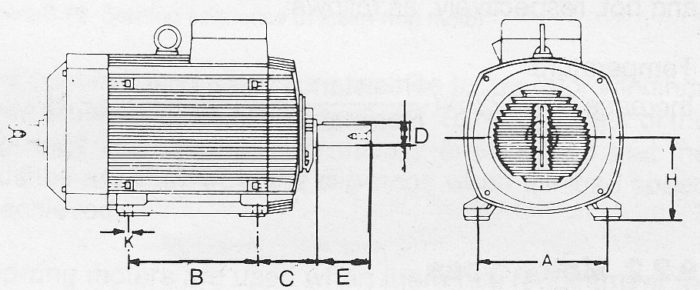
Motor size should be chosen from the above series. According to the relevant electric motor standards, dimensioning should be carried out in the manner shown in figure 6.12c using standardized dimensions. Interchangeability is thus facilitated between different manufacturers. It should be pointed out that when purchasing replacement motors, especially for older electric pump motors, checks should be carried out to ensure that the old motor was delivered after this standardization was fully implemented.

Figure 6.12c Standard dimensions for electric pump motors
Designation for main dimensions, for pump motor mounting
A = Distance between centre lines of fixing holes (end view)
B = Distance between centre lines of fixing holes (side view)
C = Distance from centre line of fixing holes at driving end of motor to shoulder of shaft
D = Diameter of shaft extension
H = Distance from centre line of shaft to bottom of feet
K = Diameter of holes in feet or mounting pads of machine
E = Length of shaft extension from the shoulder
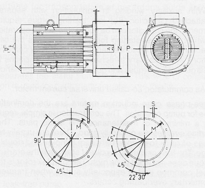
Designation of dimensions for flange mounted pump motors

M = Pitch diameter of fixing holes
N = Spigot diameter
P = Outside diameter of flange
T = Depth of spigot
S = Fixing hole diameter
Fixing dimensions for flange-mounted motors with mounting arrangement
