2.2 Pump selection for viscous liquids
Pump selection for viscous liquids
Pump selection for viscous liquids is an important factor in pump selection. Often positive displacement pumps are chosen but in many cases centrifugal pumps can be used as well. Viscosity is a fluid property which can be expressed as it´s resistance to shear and pump selection are greatly affected of the viscosity of the liquid.
There are a few established models for how to compensate and recalculate pump curves for viscosity, see bottom of this page.
The effect is dependent on the magnitude of volume rate of flow and delivery head why this characteristic must be taken into account not only when making process pump selections but also when determining friction losses in a piping system. The viscosity effect applies mainly as shown in figure 2.21
Volume rate of flow m3/h | Limiting value, low viscosity liquids | Maximum value centrifugal pumps |
1 | 3 | 30 |
10 | 10 | 100 |
100 | 30 | 300 |
1000 | 100 | 1000 |
Figure 2.21 Approximate viscosity limits for choise of pumps
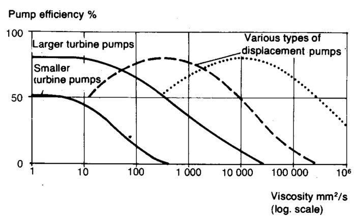
For viscosities below the limit of Iow viscosity Iiquids the principles apply to the choice of pump as given in the previous section. In the viscosity zone between this limiting value and the maximum value for centrifugal pumps both centrifugal pumps and displacement pumps can be used. The degree of efficiency of centrifugal pumps decreases as viscosity increases, whereas every type of displacement pump has a given viscosity which yields the highest degree of efficiency.

Figure 2.22 The effect of viscosity on efficiency for various types of pumps
The efficiency for somewhat larger pumps is decisive with regard to the total pumping costs and is thus a determining factor when choosing a pump. There are three different choice situations:
- For Iow viscosities apply the principles for Iow viscosity liquids.
- For medium viscosity values, both centrifugal and displacement pumps can be used. In which case the form of the Q-H curve, suction capacity, pump material, procurement costs etc. will, apart from viscosity be the deciding factors.
- For high viscosities only displacement pumps are suitable. The choice is then limited to the most suitable types of displacement pumps.
Centrifugal pump data for various viscosities
The Reynold’s number, Red for centrifugal pumps, can be defined in exactly the same way as for flow in pipes depending upon the geometrical dimensions of the pump.

where
u2 = peripheral velocity at d2 (m/s)
d2 = pump impeller outer diameter (m)
v = viscosity (Pas)
In so far as the dimensions are unknown, other Reynold’s numbers, dependent only on performance, may be used:


Where ReQ / Rep are Reynold´s numbers based on Q and H and p respectively and
Q = volume rate of flow (m3/s)
p = pressure increse (Pa)
H = delivery head (m)
n = speed (rps)
ρ = density (kg/m3)
g = 9,81 (m/s2)
The three different Reynold’s numbers acquire between themselves different numerical values which are further more dependent on the unit of speed. Rep represents the
important parameter P/vn for displacement pumps referred to in Section 3.
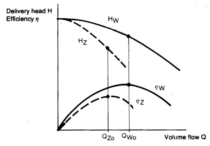
The performance of centrifugal pumps at different viscosities can be estimated from extensive series of tests with the aid of one or more of the above mentioned Reynold’s numbers. In principle pumps compared should be geometrically similar, but the available information is insufficient to permit this to be fulfilled. For classes of performance normally met with conversion can be effected by a simplified method to Figure 2.23. The figure yields factors expressing the relationship between different classes of performance obtained with viscous Iiquids and with water.

Figure 2.23 Pump curves for water, index W, and viscous liquid index Z. The point with the best degree of efficiency (BEP) is thereby moved from QW0 to QZ0.
Studying figure 2.24 below it is apparent that a pump cannot always be chosen with respect to the optimum efficiency (index O). For this purpose readings are made from the different curves for Q/Q0. Using the same diagram a “water curve” can also be converted to viscous liquids. The procedure is the same as in the example below figure 2.24, but Qw and Hw are used instead of QZ and HZ respectively.

Figure 2.24 Diagram for the determination of correction factors for the water data of centrifugal pumps from given values for viscous liquids.
Example:
Assume that QZ = 170m³/h, HZ = 30m and viscosity 206 cP. The diagram yields kQ = 0,94; kH = 0,92 for 1.0 Q/Q0 (i.e. for optimum efficiency) and kη = 0,64. The choise of shall now be determined from the water data, thus:
The efficiency will be ηz = kη * ηmax w
Established models for pump curve compensation at viscous fluids:
- A.J. Stepanoff, works good when calculating for duty points (DP) close to BEP but accuracy decrease as DP moves away from BEP.
- Paciga metoden, improved version compared to Stepanoff with a larger spann of operation with flows that can deviate from BEP. The Paciga model includes the pump specific speed the drawback is that accuracy decrease with increased viscosity.
Both Stepanoff and Paciga are based on Reynolds.
- Hydraulic Institute (ANSI/HI guideline 9.6.7-2010) based on correction factors for flow, head and efficiency used to calculate the pumps performance with the intended viscosity compared to water. Correction factors are obtained from a diagram. This methode is the prefered model which is now practiced by most users nowadays thanks to its simplicity, accuracy and wide area of use.


