
3.1.8 Pump similarity and affinity laws
Pump similarity and affinity laws
Pump similarity and affinity laws makes it possible to recalculate the performance of a pump under certain conditions, in a specially simple manner so as to be valid for all sizes of pump at different operational speeds.
These conditions are as follows,
- The pumps compared should be geometrically similar.
- The pumps compared should operate at similar operational points, i.e. with geometrically similar velocity diagrams.
- Any difference in efficiency may be neglected.
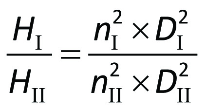
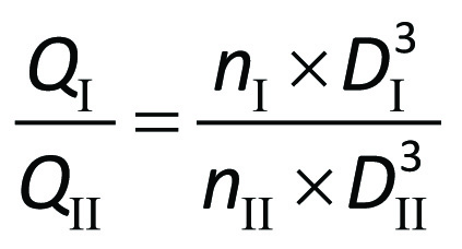
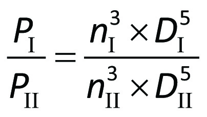
In comparison between two pumps I and II, which fulfil these conditions, the following relationship between their respective speeds nI and nII, dimensions expressed as the
diameters DI and DII, and their performances will apply.
For the delivery heads
For the volume flow
For the power requirements
Affinity laws
The affinity laws which apply to one and the same pump, comprise a special case of the general similarity relationships. When DI = DII then.
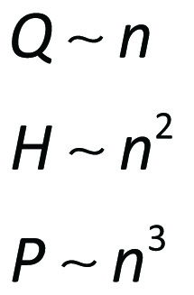
The sign ∼ is read proportional to
When the principles of similarity are used in practice, the alternation in efficiency between the pumps compared is ignored. Similar pumps have the same blade angles. Geometrically similar velocity diagrams imply the same flow angles. The inlet flow direction, which is so important for the hydraulic losses, is therefore unaltered in the cases compared. Against this background an unaltered hydraulic efficiency would seem to be a reasonable approximation. Since the impeller friction efficiency and the volumetric efficiency also maintain their values under the given conditions the assumption of unaltered total efficiency applies with a good degree of accuracy, at least when the different speeds and diameters are somewhat alike. In the case of very large pumps which are tested by means of model tests in the laboratory, a somewhat higher efficiency can be expected for the full-scale pump than that which is measured during the model test.
Figure 3.18 show performance curves for different external diameters of impeller, i.e. the different performances which can be attained for one and the same pump by replacing or reduce the impeller diameter by machining. When changing pump performance by machining or trim the impeller, the affinity laws are used to calculate the trim. Make sure the calculated trim is not to large before machining, if the impeller has been machined to much it will not give sufficient head and flow. As a good rule of thumb when machining an impeller after proper calculation with affinity laws, do not machine more than 70 percent of the calculated reduction. It will most probably not result in the ideal impeller diameter but it will save a lot of the troble cutting away to much.
With moderate alterations of the impeller diameter the NPSH-curve is not affected to an extent where it has to be taken into account and also the efficiency curve is only affected to an insignificant degree but the general recommendation is to check with the pump supplier prior to machining.
In the absence of pump performance test data for different diameters then the alteration in performance in the case of reduction in the outer diameter from D1 to D2 according to figure 3.17 can be estimated according to the following rule of thumb (Equ. 3.18e):


In the Q-H diagram the new approximate curve is obtained by recalculating a number of points, see figure 3.18

With moderate alterations of the impeller diameter the NPSH-curve is not affected to an extent where it has to be taken into account and also the efficiency curve is only affected to an insignificant degree but the general recommendation is to check with the pump supplier prior to machining.
If the pump speed is altered then a different performance is obtained which is also expressed as a series of curves in the Q-H and the Q-P diagrams. An existing pump curve with Q-H and Q-P diagrams is recalculated from, for example, a maximum speed to some other speed by recalculating 4-5 points on the maximum curves one after the other to the new speed With the help of the affinity laws and the transmission efficiencies for the actual speed converter. Figure 3.22 shows an example of such recalculated pump performances. A more detailed treatment of speed regulated pumps recurs in Chapter 8.

Figure 3.18c Examples of performance curves for a speed regulated pump. The power requirement relates to a pump with hydro-dynamic safety coupling. The speed is expressed relative to the full speed of a constant speed pump