
10.7 Pump speed
Pump speed
Pump speed control and performance are determined by the laws of affinity. For centrifugal pumps, i.e. radial, semi axial (also referred to as diagonal pumps) and propeller pumps, the so-called affinity laws govern performance at speeds n1 and n2 thus:

Equation 10.7c for power applies only to the shaft power of the pump Pp. Equation 10.7a applies to centrifugal as well as displacement pumps. H and P are determined by the pressure head of the system, i.e. by the system curve. For further explanation of the affinity laws see Chapter 3, Section 3.1.8 Pump similarity and affinity laws >>>
The various efficiencies have to be taken into account when working out the power requirement for the complete pump aggregate, as in figure 10.7d.
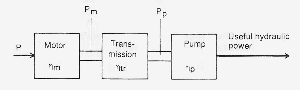
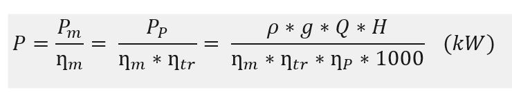
Thus for drive power P:
Where speed regulation is used, some form of speed converter is required in order to obtain the required pump speed. Such a converter usually causes power losses < 1% , which cannot normally be neglected.
Efficiencies with various methods of pump speed control
If the affinity laws are applied to a centrifugal pump then, when the pump speed is regulated down to half speed, the volume flow also reduces by a half, the delivery head to a quarter and the power required at the pump shaft to an eighth. Similarly, when regulating down to 20% of maximum speed the pump shaft power goes down to 0.8% of the power at maximum speed, i.e. it is difficult to verify the affinity law by measurements made in actual operation.
Seen against the rapid change of pump power with speed, the method and efficiency of altering pump speed is of very little importance. In practice, it means that many drive arrangements and transmissions which themselves display poor transmission efficiencies give extraordinarily good results for pumps. The methods available can be divided into three main groups:
Group A includes those arrangements with comparatively high efficiencies over a wide range of speeds. These arrangements are intrinsically ‘”almost loss-free” with constant efficiencies across the full range of speed.
Group A:
- Mechanical variators
- DC motors with thyristor rectifiers
- Slip-ring induction motors with cascade converters
- Induction motors with frequency converters
- Synchronous motors with frequency converters
- Commutator motors.
In practice, however, the efficiency will fall off at reduced speeds, because certain losses do not reduce as rapidly as the useful power. These losses will probably be frictional losses, power for the cooling fan, etc.
The characteristic of Group B is that the design and construction of the transmission results in an efficiency which reduces in direct proportion to the output speed. It includes those transmissions which work with the same torque on the input and output shafts, for example hydrodynamic couplings. Slip regulated induction motors, regulated by primary voltage or resistance, belong to this group.
Group B:
- Hydrodynamic coupling
- Hydrofrictional coupling
- Resistance regulated, slip-ring induction motor
- Primary voltage regulated induction motor
- Eddy current coupling.
Group C consists of the hydrostatic transmissions, hydraulic motor plus hydraulic pump, with either pump or motor having variable displacement. This system has a lower peak efficiency at full speed than other alternatives because of losses from friction and internal leakage. Internal leakage increases with time because of inevitable wear.
Approximate transmission efficiencies η1 for Groups A, B and C are represented in figure 10.7b.

Conversion of pump curves to various speeds
For any given pump, i.e. any given system curve in accordance with figure 10.7c, the minimum required speed, nmin can be calculated from the following equation.
nmin = nmax * √(Hstat/Hmax ) (Equ. 10.7e)
The lowest required speed often has to be known when selecting equipment used for speed regulation.
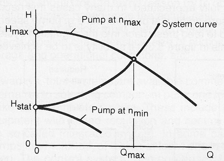
Figure 10.7c Relationship for lowest required pump speed, nmin
The performance of speed regulated pumps is usually described as a family of curves for Q-H and Q-P as shown in Chapter 3, Section 3.16 Centrifugal pump curve >>> The curves there were determined by means of the affinity law, equations 10.7 a-c.
The power requirement in accordance with equation 10.7c refers to the power requirement at the pump shaft. The power requirement for the electric motor is obtained by dividing by the efficiencies of both the motor and the transmission, see also figure 10.7a.