
1.4.1 Pump sump submersible sewage pumps
Pump sump for submersible sewage pumps
Pump sump for submersible sewage pumps are mainly a concern for sewage pumps with a volume rate of flow exceeding 100-200 l/s, i.e. for medium-large and large pumps. To a considerable extent these directions also apply to pump sumps for storm water and rain water. In these pump sumps we are not confronted with problems of sewage sediment but rather with problems of sand.
A pump sump for submersible sewage pumps must have a sufficiently large volume so as to avoid too frequent starting and stopping of the pumps, otherwise there is a risk of the pump motors becoming over-heated. The problem of air being whipped into the water, the so-called waterfall effect, arises if the inlet to the sump is located above the surface of the liquid. In such cases it is necessary to ensure that the pump sump is designed so that the water is vented before it reaches the pumps. Otherwise there is a risk that the pumps will run unevenly, vibrate and even stop pumping if the amount of air in the water is too great. Air eddies are a problem which can also cause pumps to operate unevenly and set up vibrations. Often these eddies originate at the pump in-akes and can be reinforced into a vortex if the pump sump is incorrectly designed. In the case of totally calm liquid surfaces it is, for example, necessary to have greater submersion depths in order to avoid eddies other than those required when the liquid surface is disturbed.
The inlet pipe for pump sumps for submersible sewage pumps must be located in such a way that the flow of liquid to the pumps may be fairly evenly distributed. If the flow pipe to the sump discharges immediately in front of a pump, there is considerable risk of disturbance to the pump intake. This can increase or reduce the power consumption of the motor at the sametime as the capacity of the pump is changed. In extreme cases this can cause the motor protecting device to be activated. The formation of sludge, of both the floating and the sedimentary kind, must also be borne in mind when designing a pump sump. It must be designed to prevent the formation of dead zones with motionless water. Similarly it must be possible to pump away floating sludge at regular intervals.
Pump sump volumes for on-off regulation are dealt with in detail in Chapter 8.
Four alternative solutions are given for pump sumps with different locations for intake pipes according to intake pipe locations. The dimensions of the pump sump are calculated according to the volume rate of flow per pump. The dimensions A-E for the different designs are determined by using the nomogram, figure 1.4.1a.
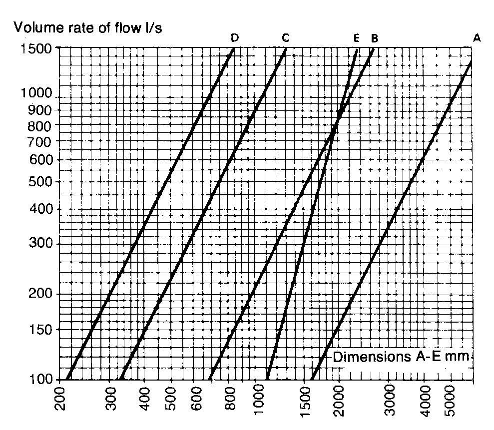
If the available height is not sufficient, the volume required is most easily obtained by increasing dimension A.
Remarks:
- Dimension B: The unobstructed distance between two pump housings should not be less than 200 mm.
- Dimension C: The unobstructed distance between a side wall and pump casing must not be less than 100 mm.
Alternative 1. Intake at right angles to and high up in a special intake chamber
Intake at right angles to and high up in a special intake chamber, Figure 1.4.1b Due to the high location of the inlet pipe, much air is whipped into the inflowing water. Thanks to the design of the intake chamber, there is time for the water to be vented before it is led into the pump chamber through holes in the bottom of the intake chamber. The side wall (section X-X), which is extended at least half way up the motor housing, prevents the formation of between the outer pump and the side wall.
The continual movement of the water means that the risk of sedimentation is minimal, provided that the minimum dimensions are not too greatly exceeded.
The dividing wall (baffle) immediately opposite the inlet must be high enough to be reached by the in flowing water. A weir can be arranged at the side so that floating waste can be removed by pumping.
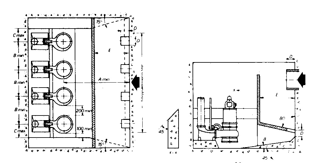
Figure 1.4.1b Alternative 1
Alternative 2. Intake from the side and at the bottom of a special intake chamber
Intake from the side and at the bottom of a special intake chamber. Figure 1.4.1c. This is a variant of Alternative 1. The square openings in the inlet chamber are necessary to spread the flow throughout the entire pump sump and to remove any air which may still become whipped into the in flowing water. Compared with Alternative I, the flow conditions in the pump chamber are somewhat more uneven and turbulent. The breadth of the intake chamber and the height of the baffle are calculated with respect to the diameter of the inlet pipe, the former 1.25 x the diameter and the latter 0.75 x the diameter.
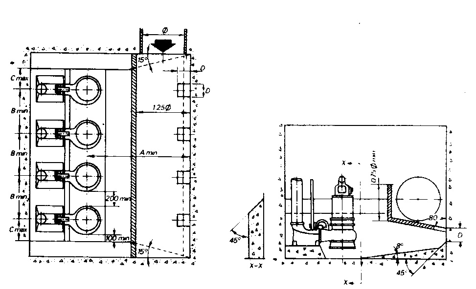
Figure 1.4.1c Alternative 2
Alternative 3. Inlet from the side and in the bottom of the pump sump
Inlet from the side and in the bottom of the pump sump. Figure 1.4.1d. A partition wall separates the pump sump and forms a kind of intake chamber. From this chamber water flows through square openings with measurements 2D x D located immediately in front of every pump. The openings are dimensioned so that the flow velocity through them does not exceed 1 m/s. In this manner the water is led without risk of eddies forming or of sedimentation at the pump intakes.
The partition wall should be at least high enough to reach up to a point on a level with half way up the pump motor housing. At the same time its height should not exceed a level situated a little below the highest starting level, thereby making possible the removal of floating waste by pumping. The breadth of the intake chamber shall be 1.25 x the diameter of the inlet pipe, provided that the maximum flow velocity in the inlet pipe does not exceed 3 m/s. The distance between the pump center lines and the wall can be as little as 0.5 x A.

Figure 1.4.1d Alternative 3
Alternative 4 Inlet located at the of the pump sump at 90° to the row of pumps
Inlet located at the of the pump sump at 90° to the row of pumps. Figure 1.4.1e. This is a simple and functional arrangement which gives a smooth turbulent-free flow to the pumps. The conical inlet section should have an angle of 60-75°. The distance between the pump centrelines and the end of the inlet section should not exceed 0.5 x A.
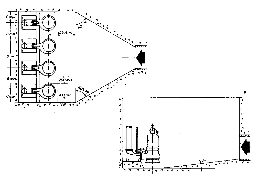
Figure 1.4.1e Alternative 4
Sometimes there is a demand that it should be possible to empty the inlet pipe to the pump sump at the lowest water level (lowest stop level) in the pump sump.
Alternatives 1 and 2 meet this requirement. In the case of Alternatives 3 and 4, connection may made according to figure 1.4.1f
If we do not follow this model but allow the inlet pipe to discharge directly above the lowest stop level in the pump sump, we are confronted in the case of major flows with the problem of air being introduced due to the waterfall effect.
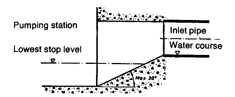
Figure 1.4.1f Recommend connection of inlet pipe to the bottom of the pump sump.
Separators, such as screens or filters, should be provided on the suction side of the pipe to protect the pump against contaminants.