3.72 Sewage pumping station
Sewage pumping station
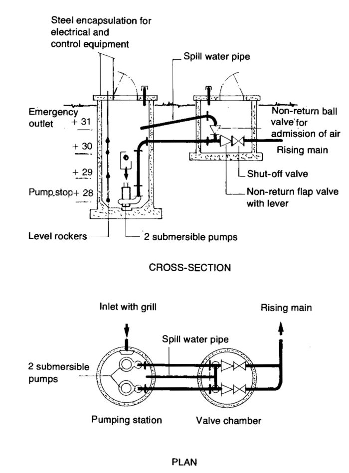
The small sewage pumping station serves e.g a housing area. The supply of sewage during the initial period is a minimum of approximately 1 l/s (liters/second) and a maximum of approx. 5 l/s. It is estimated that gradually the minimum flow will increase to 2 l/s and the maximum value will increase to about 8 l/s. The positive elevations at the pumping station are shown in figure 1. The rising main from the station is about 700 m (metres) long and discharges into a well at level +55 m. The diameter of the pipe is 150 mm and the volume is thus approx. 12,4 m³.
As may be seen in the figure, pump stop at +28 m. The station has an emergency outlet (spillway) at level +31 m. The static delivery head Will be maximum 55-28 = 27 m and minimum 55-31 = 24 m. The stop level of the pumps has been placed as low as possible, approx. 0,25 m above the floor in the pump sump, in order to avoid the formation of sludge deposits.

The station consists of two units, the pumping station itself and a valve chamber. The pumping station is constructed of concrete rings with rubber-ring-sealed joints. The internal diameter is 2 m and the volume per metre of height is thus about 3,14 m³. The station is equipped with two identical submersible centrifugal turbine pumps with supports and guides so that lifting can be effected. The pumps are started and stopped via level rockers, one of which is also used to transmit a signal to the control center when the water level in the station is too high.
In the valve chamber, which is also constructed of concrete rings, there is a system of valves which ensures reverse-flushing of the pumps at every stop to prevent clogging. During pump shut down air is introduced into the system via the non-return ball valve, the ball should have a specific gravity of 0,9 kg/dm³ to function efficiently, and the water in the rising main in front of the flap non-return valve flows back to the pumping station and flushes the pump clean. The amount which flows back in this particular case is about 90 litres. Thus for a short time the pump rotates backwards.
When the pump starts up it is impossible to prevent a slight jet of liquid being expelled through the non-return ball valve as this cannot be closed instantaneously. A spill water pipe returns the liquid to the pumping station.
System and pump curves
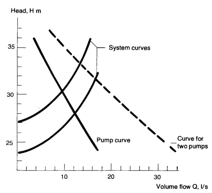
These are illustrated in figure 3.72b. As stated above, the static rising delivery head can vary between 27 m (pump stop level) and 24 m (emergency outlet level). The losses in the rising main and its valves are shown by the system curves. The size of pump chosen has volume rates of flow from 9 to 12 l/s, depending on the delivery head. Figure 3.72b also shows the curve for pumps in operation. The efficiency of the pumps in the operating zone is about 70%. The size of the motor is 9.6 kW, the normal output being about 6 kW, corresponding to a current of about 12A (Amp). The pumps are direct-started.

Figure 3.72b. Sewage system curve and pump curve.
Operating conditions
As mentioned in the introduction, the flow of water to the station in the initial period is 1-5 l/s. The volume of the pump sump is about 3140 liters/metre. Pumping should occur at least once every hour to ensure water replacement. The start level of the first pump has therefore been provisionally adjusted to level +29 (see figure 3.72a), i.e. when 1 m of the sump is utilized.
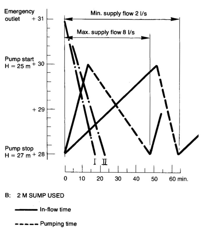
The operating circumstances will then be as shown in figure 3.72c. At minimum supply flow the sump used is filled in about 52 minutes (3140/1 * 60) and pumping takes place for about 6 minutes (out-flow approx. 10 l/s at H mean 26,5 m, see figure 3.72b, minus in-flow, i.e. 3140/(10-1)*60).
As already mentioned, the volume of the rising main is 12,4 m³ and after 4 hours the water in the pipe has been replaced. At maximum in-flow the sump is filled in 10,5 minutes and pumping out takes equally long, pump start occurring every 21 minutes.

Gradually as the minimum and maximum rates of flow are increased, the sump volume will also be increased. Figure 3.72d illustrates operating conditions at full supply flow and when 2 m of the sump (volume 2 x 3140) is to be used. This figure also includes two curves, I and Il, showing the time required for the emptying of the station from the emergency outlet level, e.g. after a power failure, with one pump in operation and minimum supply flow (l) and both pumps in operation and maximum supply flow (Il). In the times no allowance has been made for the reverse-flushing flow volumes. These, however, would exercise a marginal effect only.

Figure 3.72d In-flow and pumping times.
As may be seen from the normally only one pump is required to change over takes place at every pump start so that both units are used. The second pump therefore acts as a reserve and is started up when the level in the station exceeds the permissible value, i.e. when the first pump refuses to function or its capacity is reduced. The station is monitored via an alarm system and is visited for inspection only once a week, when the sump is flushed clean and functional checks, etc., are carried out.
