3.2.6 Submersible deep well pumps
Submersible deep well pumps
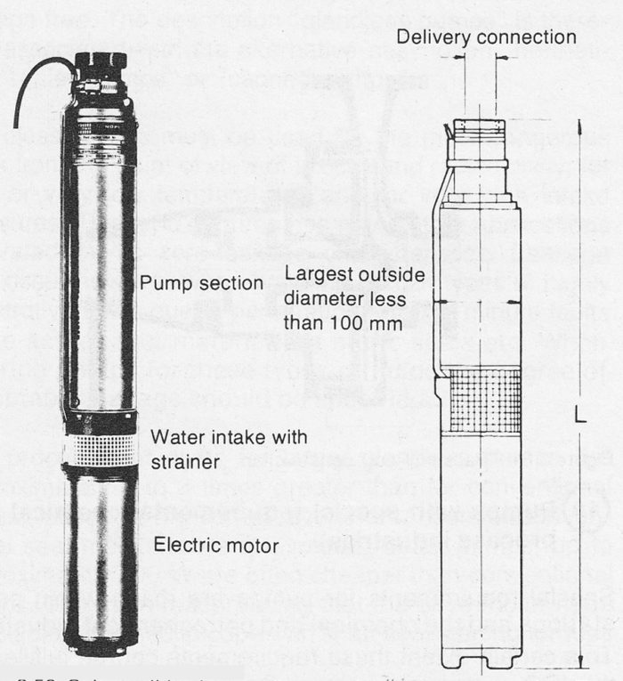
Submersible deep well pumps in smaller sizes have the same range of applications as deep-well pumps with ejectors. The difference here being that the pump is placed directly in the borehole connected by means of a delivery hose and electric cable. Since the smallest borehole diameter is 4″ the diameter of the pump must be somewhat less, see figure 3.661. The pump is a multi stage centrifugal pump driven by a special type of long and narrow electric motor located beneath the pump and cooled by the water in the borehole.

Figure 3.261a Submersible deep well pump for “domestic supply”. The pump Iength L varies according to the depth of the borehole between 500 and 2500 mm.
Submersible deep well pumps of larger sizes have outside diameters of up to approx. 500 mm and Iengths of up to approx. 5 metres. Their hydraulic data varies considerably, the max values being; rate of volume flow approx. 5000 m³/h and delivery head of up to approx. 1000 m. Motor outputs of several thousand kW are available when using high voltage motors.
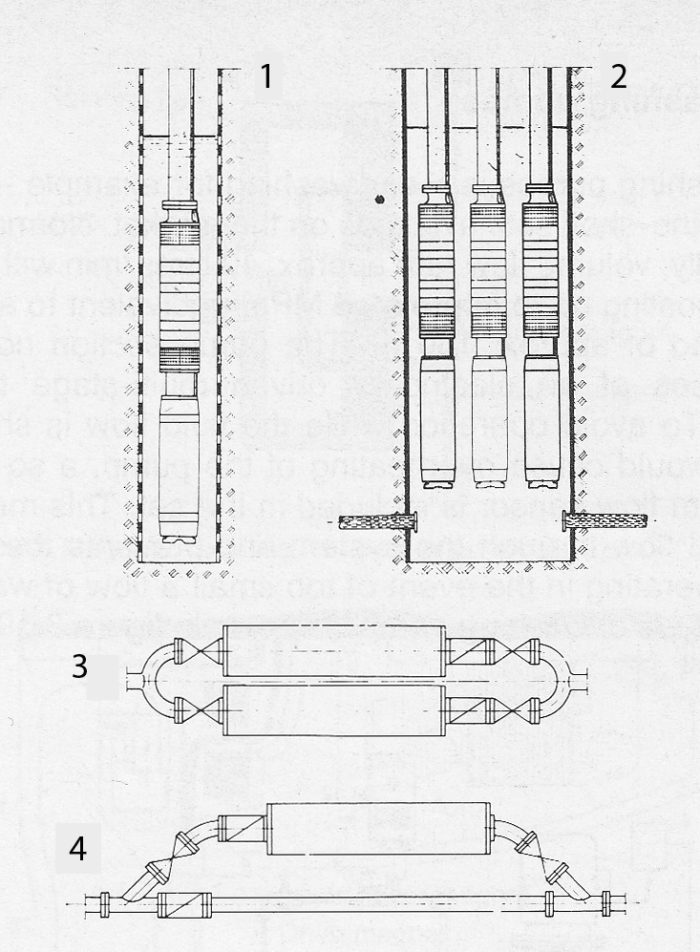
They are used for drinking water supply, reduction of ground water levels and mine drainage. Typical applications are to be found in restricted wells or shafts, figure 3.261b. They can also be used for pressure boosting in drinking water supply networks, whereupon the pump may be integrated in a section of pipe.

Figure 3.261b Deep well pumps placed in wells, illustrations 1 and 2 and placed as a pipe section for pressure boosting illustrations 3 and 4.
The electric motors are always squirrel cage, fluid filled, induction motors, which naturally makes very great demands upon the motors electrical insulation. The fluid filling is either water, water oil emulsion or oil, depending on the requirements of each specific case. The fluid filling is separated from the pumped fluid by a mechanical seal and a diaphragm to compensate for variations in volume, due to temperature changes for example. The pump and motor rotors run in fluid lubricated plain bearings.
The axial thrust bearing is the most heavily loaded, which is why some manufacturers use hydraulic constructions employing opposed impellers. Special models are available for sand contaminated or corrosive water.
Figure 3.261c Principle design of larger deep well pump

